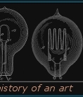
Just finished this tonight, used the cabinet of an old defunct radio for this project. The power supply consists of two transformers connected together, giving me full isolation from the main AC line. The first transformer has multiple taps (pilfered from a nonworking VCR) and connects to the C6 tester and second transformer. The second transformer steps the LV from the 1st xfmr back upto 120v, which connects to a bridge rectifier, then onto the C7 and C9 testers. Voltage control to each bulb is handled by NPN Power transistors and a 100k pot (50k on the C6). This works well for slowly bringing up even the oldest lamps. the control end doesn't exactly look pleasant (used whatever was near me at the time). The photos below show the assembly (No shots of the electronics as of yet). The second photo shows three bulbs (C6/7/9) being operated at low power levels on the tester At this level you can see the fine details of the blue MAZDA C9 lamp on the far right.